
What is Pattern Shrink and How Does it Affect Your Casting?
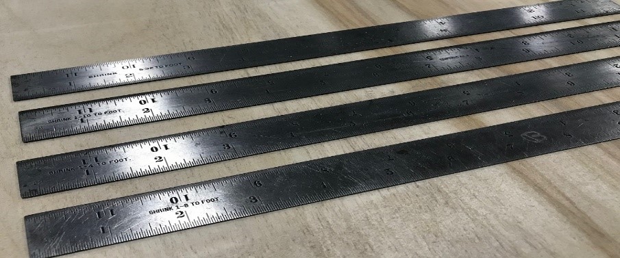 |
Pattern shrink, not to be confused with the casting defect shrinkage porosity, is an allowance made on patterns, molds, and cores to compensate for the dimensional changes as a casting cools. This is traditionally applied by patternmakers using shrink rules, which are scaled rulers used in the production of tooling for metal casting. Today, “shrink” is more commonly applied as a scale factor to the 3d CAD file during tool build.
For instance, the shrink rate for ductile iron can vary from as little as zero, on up to 1%, or 1/8” per foot, from one metal caster to the another. Another contributor to variation is part geometry (section thickness & shape, the presence of ribs, bosses, etc…) and the use of cores and/or inserts in the mold. Generally speaking, a complex geometry will have a less predictable shrink rate.For rigid molds (airset/dry-sand, permanent mold, die casting, etc…), the shrink rate is generally considered linear and encompasses the dimensional contraction of the part after the metal has solidified. For weak molds (i.e. green sand), mold wall movement during pouring and solidification of the metal can play a role in affecting the shrink rate to be applied. It is usually expressed as a percentage, or a fraction of contraction per foot, although the shrink for a given material can vary depending on the foundry.
Because of the variables involved, pattern shrink is essentially an educated “best guess” of how the casting will contract after solidification and should not be considered universal across the industry, although most foundries generally use a similar shrink for a given material.
Since it is linear, as a casting gets larger the total amount of shrink a part will experience as it cools is greater, which magnifies the effect of pattern shrink error. (i.e. the shrink applied vs the actual shrink experienced)
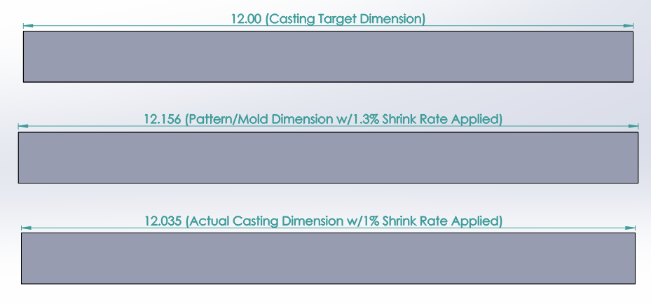
To illustrate, the pattern for an aluminum casting 12.00” long with a shrink rate of 5/32 per foot applied, or 1.3%, would be built to 12.156” long. (12.00 x 1.013 = 12.156) However, the actual shrink a casting experiences may yield a part a little short, or long, of the 12.00” dimension once cooled. If the actual rate is 1.0%, then the casting would measure 12.035” long, the extra .035” of length being attributable to the error in shrink allowance.
 |
Those same conditions (1.3% applied shrink vs 1.0% experienced) applied to a much larger part, say 50.00” long, would have a pattern 50.65” long (50.00 x 1.013 = 50.65) and result in a casting 50.144” long, or .144” longer than anticipated. This is obviously a much larger deviation from the nominal dimension than the shorter 12.00” part experiences. (.144” vs .035” oversize)
For this reason, casting tolerances should be graduated and allowed to grow as the part becomes larger. ISO 8062 specifically addresses this issue using established tolerance grades, which are applied based on generally accepted process capabilities and characteristics. An investment casting may use the more restrictive DCTG-7 tolerance grade, while a sand casting may require the allowances afforded using DCTG-9 or DCTG-10.
It is important to recognize that pattern shrink plays a vital role in driving the final casting dimensions and can affect downstream processes, such as machining. It is the responsibility of the foundry and pattern shop to coordinate their efforts to ensure the shrink applied is appropriate to the metal, foundry, and processes used. Utilizing industry accepted tolerancing standards, such as ISO 8062, will allow the foundry to produce parts within spec and ultimately contribute to keeping costs in check.